
Welcome to My Homemade Incubator and Automatic Egg Turner
First thing you have to know about me is I am NOT going to spend any big money on anything. I can always make it myself, with a little help from my friend also sir. We are remodeling so I just so happened to have cabinets laying around taking up room. I also just happened to get addicted to chickens about the same time. So now that i have my bigger chickens settled into their new coops/pens I just had to start a new project. So first things first the cabinet. It is a 30" base cabinet that had sliding trays we are using for the egg turner trays. I took out the drawers in the top and replaced the back wall with plywood just to make it stronger.
What we need
Egg turner motor

This motor is a 5 RPM 12V DC motor for the IncuKit DC. Use this motor to make your own egg turner. The IncuKit DC allows you to set an interval so the motor will turn on for a few seconds every few hours (Customize to your own turning needs)
RTC module

This a link How it's work
http://tronixstuff.com/2014/12/01/tutorial-using-ds1307-and-ds3231-real-time-clock-modules-with-arduino/
We keep getting requests on how to use DS1307 and DS3231 real-time clock modules with Arduino from various sources – so this is the first of a two part tutorial on how to use them. For this Arduino tutorial we have two real-time clock modules to use, one based on the Maxim DS1307:
Arduino nano


The Arduino Nano USB Microcontroller v3 (No Headers) is a breadboard ready version of the with integrated USB. The Nano has everything that the has (electronically) with more analog input pins and an onboard +5V AREF jumper. The Nano automatically senses and switches to the higher power supply, so there is no need for a power select jumper.
The nano's pin layout works well with the Mini or the Basic Stamp (TX, RX, ATN, GND on one top, power and ground on the other). The Arduino Nano USB Microcontroller v3 (No Headers) can be powered via the mini-B USB connection, 6-20V unregulated external power supply (pin 30), or 5V regulated external power supply (pin 27). The power source is automatically selected to the highest voltage source. The package contains only the microcontroller.
The nano's pin layout works well with the Mini or the Basic Stamp (TX, RX, ATN, GND on one top, power and ground on the other). The Arduino Nano USB Microcontroller v3 (No Headers) can be powered via the mini-B USB connection, 6-20V unregulated external power supply (pin 30), or 5V regulated external power supply (pin 27). The power source is automatically selected to the highest voltage source. The package contains only the microcontroller.
Features:
• Automatic reset during program download
• Power OK blue LED on the bottom
• Green (TX), red (RX) and orange (L) LED
• +5V to AREF jumper
• Auto sensing/switching power input
• Small mini-B USB for programming and serial monitor (cable not included)
• ICSP header for direct program download
• Power OK blue LED on the bottom
• Standard 0.1" spacing DIP (breadboard friendly)
• Manual reset switch
Pin diagram Arduino nano

Relay module
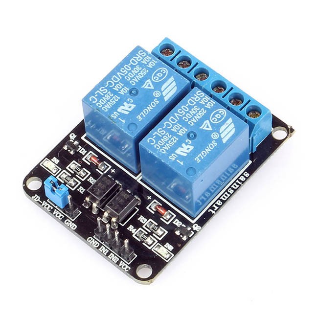

How to use relay modules to control AC devices?
A relay is an electrically operated switch to control high power/voltage or AC household devices using low-power signals from a microcontroller, etc. Many relays use an electromagnet to operate a switching mechanism mechanically, but other operating principles are also used. Relays are used where it is necessary to control a high power/voltage circuit by a low-power signal (with complete electrical isolation between control and controlled circuits), or where several circuits must be controlled by one signal. The most common types of relays that are used in the relay modules are the 12V SPDT (Single pole, Double Throw) type relays.
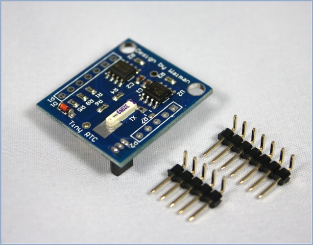
Arduino Tiny RTC I2C Real Time Clock
This Arduino Tiny RTC I2C module incorporates the DS1307 I2C real time clock IC and the 24C32 32K I2C EEPROM storage. What's more, it has a DS18B20 temperature sensor on board. All of this in a tiny package of 25mm x 28mm x 8.4mm. It comes with a LIR2303 rechargeable lithium battery, and a charging circuit is included in the module. When the temperature sensor is off, the RTC module can run for 1 year on a single charge.
This module is used for applications such as datalogging, timing applications ex. turning on the sprinkers at 4pm in the evenings. Since the module is self powered the time data is maintained even if the Arduino is powered off, allowing for building low power systems which can run for a long span of time without change of batteries.
Specs of DS18B20 Temperature Sensor
- 3.0-5.5V input voltage
- Waterproof
- -55°C to+125°C temperature range
- ±0.5°C accuracy from -10°C to +85°C
- 1 Wire interface
Wiring the RTC to Arduino
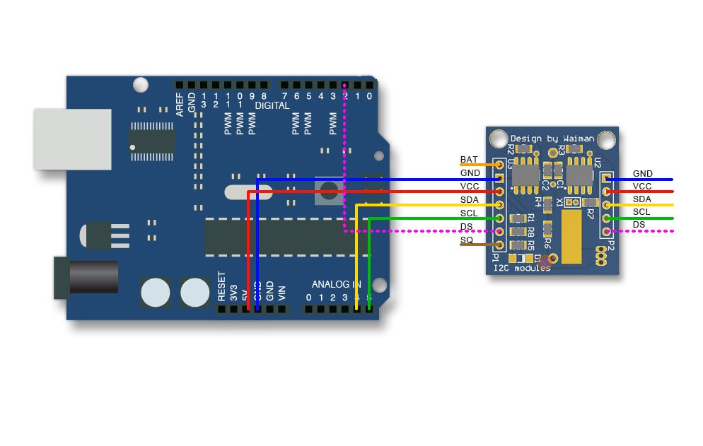
The most useful pins are duplicated from P1 to P2. If needed, the pin "BAT" can be fed into an ADC pin for monitoring the battery voltage. The pin-outs are explained below. Connecting "VCC" to 5 V will trickle charge the onboard battery.
Arduino Tiny RTC I2C Real Time Clock Pinout | ||
| PIN | Description | Comment |
| BAT | Battery voltage | To monitor the battery voltage, or not connected |
| GND | Ground | Ground |
| VCC | 5V supply | Power the module and charge the battery |
| SDA | I2C data | I2C data for the RTC |
| SCL | I2C clock | I2C clock for the RTC |
| DS | DS18B20 Temp. Sensor output | One wire inteface |
| SQ | Square wave output | Normally not used |
The I2C wires "SDA" and "SCL" are the data line and clock line, they should be connected to the corresponding pins depending on the Arduino board.
| Board | I2C / TWI pins |
| Uno, Ethernet | A4 (SDA), A5 (SCL) |
| Mega2560 | 20 (SDA), 21 (SCL) |
| Leonardo | 2 (SDA), 3 (SCL) |
| 20 (SDA), 21 (SCL), SDA1, SCL1
For more detail, please visit the Arduino Wire Library.
Now it's time to connect relay module
1.VCC 2.GND 3.COM 4.signal 4.Normally open 5.normally close Now connect a relay VCC to Arduino 5v. Gnd to arduino GND. Your motor pin connect a relay normally open. And connect a arduino difine a any digital pin to relay signal pins. And also connec a adapter nutral to relay com pin. Also Aadptar anoither wire & motor another wire to jointed. Now connect a RTC to Arduino WE can use a only VCC,GND,SDA,SCA pins only. Now connecta rtc VCc to arduino Vcc And connecta rtc GND to arduino Also connecta rtc sda pin to arduino A5 pin. Also connect a rtc scl pin to arduino pin A4 . |


0 टिप्पणी(ण्या):
टिप्पणी पोस्ट करा