
TEMP/humidity sensor project
I am going to show you how I made a temp and humidity sensor with an Arduino Uno. My end goal is to make one with an Attiny84 and etch a PCB for it. While I do have the parts and pieces to do this, the weather outside is not cooperating. It is hard to etch a board in my garage at less than 10 degrees Fahrenheit. That will be a different instructable for a later date.
Thanks again for taking time to read my project.
To start out, the following is required for this project:
All parts can be purchased at sparkfun or adafruit. Or you can do as I do and salvage as much as you can from old devices.
- Arduino (I used an UNO R3, but 5V any will work)
- Breadboard
- DHT11 temperature and humidity sensor
- 10k ohm potentiometer
- 16x2 LCD screen
- tactile button
- USB A-B cable
- Power Bank
- Jumper Wires

Now it is time to attach all the wires to the
devices. Please refer to the Fritzing schematic (please note I do not
have jumper wires between the two power rails on the breadboard. you
will need them if you use both):
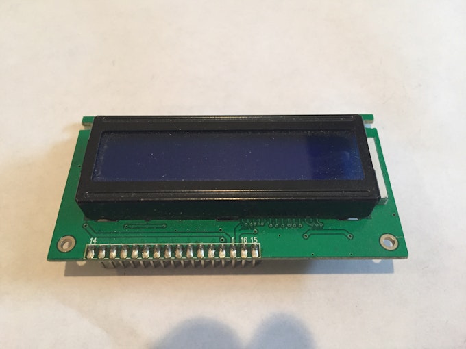
The LCD
display I am using was recovered from an old fire alarm annunciator
panel. Pins 15 & 16 are located before Pin 1 and instead of Pin 16
being Gnd, it is actually 5v and Pin 15 is Gnd. Please double check your
own display and make sure your pins are correct. As my display pinout
is most likely different from almost everybody else, I have made the
Fritzing schematic with the "standard" display instead of my exact
pinout.
Uno
Gnd --> negative rail on breadboard
5v --> positive rail on breadboard
DTH11
Pin1 --> 5v and 10k ohm resistor
Pin2 --> Arduino Pin8 and 10k ohm resistor
Pin3 --> no connection
Pin4 --> Gnd
16x2 LCD Screen
Pin1 --> Gnd
Pin2 --> 5v
Pin3 --> 10k ohm potentiometer wiper pin ( middle pin. the other two pins on the POT go to 5v and Gnd)
Pin4 --> Arduino Pin12
Pin5 --> Gnd
Pin6 --> Arduino Pin11
Pin7 --> no connection
Pin8 --> no connection
Pin9 --> no connection
Pin10 --> no connection
Pin11 --> Arduino Pin5
Pin12 --> Arduino Pin4
Pin13 --> Arduino Pin3
Pin14 --> Arduino Pin2
Pin15 --> 5v
Pin16 --> Tactile button (other side of tack butto


// include the library code:
#include <LiquidCrystal.h>
#include "DHT.h"

// set the DHT Pin
#define DHTPIN 8

// initialize the library with the numbers of the interface pins
LiquidCrystal lcd(12, 11, 5, 4, 3, 2);
#define DHTTYPE DHT11
DHT dht(DHTPIN, DHTTYPE);

void setup() {
  // set up the LCD's number of columns and rows:
  lcd.begin(16, 2);
  dht.begin();

  // Print a message to the LCD.
  lcd.print("Temp:  Humidity:");
}

void loop() {
  delay(500);
  // set the cursor to column 0, line 1
  // (note: line 1 is the second row, since counting begins with 0):
  lcd.setCursor(0, 1);
  // read humidity
  float h = dht.readHumidity();
  //read temperature in Fahrenheit
  float f = dht.readTemperature(true);

  if (isnan(h) || isnan(f)) {
    lcd.print("ERROR");
    return;
  }

  lcd.print(f);
  lcd.setCursor(7,1);
  lcd.print(h);
}

Complete finished work this circuit looks like this
thanks for the watching this blogger


0 टिप्पणी(ण्या):
टिप्पणी पोस्ट करा